


JINYUAN
JINYUAN
JINYUAN
JINYUAN
JINYUAN
JINYUAN
JINYUAN
JINYUAN
JINYUAN
JINYUAN
JINYUAN
JINYUAN
JINYUAN
JINYUAN
JINYUAN
JINYUAN
Content
- 1 Preparing the Foundation Before Pole Erection
- 2 Erecting the Tapered Steel Pole
- 3 Assembling the Lighting Platform and Luminaires
- 4 Electrical Wiring and Grounding Connections
- 5 Testing the Raise-Lower Mechanism and Final Commissioning
- 6 Common Applications Where This Installation Approach Applies
- 7 Comparing Installation Considerations by Site Type
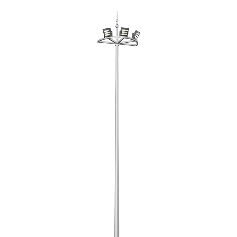
Installing high mast lighting involves five sequential stages that must be completed in order: preparing a reinforced concrete foundation sized to the pole height and wind load, erecting the tapered steel pole and anchoring it to the foundation bolts, assembling the lighting platform and luminaires either on the ground or after raising depending on the lowering system used, connecting electrical wiring and grounding conductors according to the design drawings, and finally testing the raise-lower mechanism along with the full lighting circuit before the site is considered operational. Because these poles commonly reach heights between twenty and forty meters, foundation work and structural anchoring require more precision than a standard street lighting installation, and skipping verification steps at any stage can affect long-term stability.
Preparing the Foundation Before Pole Erection
The foundation for a high mast pole carries the combined weight of the steel structure, the lighting platform, and the lateral forces generated by wind acting on a tall, exposed surface, so foundation depth and reinforcement pattern are calculated based on local soil conditions, wind zone data, and the specific pole height being installed. Foundation drawings supplied with the pole typically specify anchor bolt circle diameter, bolt length, and reinforcement steel layout, and these dimensions need to match the pole base plate precisely, since even a small discrepancy in bolt spacing can prevent proper alignment during erection.
Excavation depth commonly ranges from two to four meters depending on pole height and soil bearing capacity, with a cage of reinforcement steel placed before concrete is poured to resist the bending moments created by wind loading at height. A conduit sleeve for underground electrical cable and a separate grounding conductor path are typically embedded into the foundation at this stage, since retrofitting these connections after concrete has cured becomes considerably more difficult. Concrete curing time before the pole can be safely erected generally spans at least seven to fourteen days, depending on ambient temperature and the concrete mix design used.
Erecting the Tapered Steel Pole
High mast poles are typically manufactured as multi-sided tapered sections formed by press-bending steel plate, then hot-dip galvanized to resist corrosion during decades of outdoor exposure. Depending on total height, the pole may arrive as a single piece or in multiple sections that need to be joined on site using flanged connections and structural bolts before erection, since transporting an assembled forty-meter pole is often impractical on public roads.
Crane Positioning and Lifting
A mobile crane rated for the pole's weight and the required lifting height positions the base over the anchor bolts while riggers guide the pole into alignment, a process that typically takes a coordinated crew rather than a single operator due to the pole's length and the precision needed to seat the base plate evenly across all anchor bolts. Once the base plate rests on leveling nuts and the anchor bolts pass through the mounting holes, the pole is checked for vertical alignment using a level or laser plumb reference before the anchor nuts are torqued to the specification provided by the pole manufacturer.
Assembling the Lighting Platform and Luminaires
The lighting platform, generally framed in stainless steel and assembled with stainless steel bolts and nuts to resist long-term corrosion, holds the luminaire ring where individual light fixtures are mounted around the pole's circumference. Depending on the system design, this platform is either fixed near the pole top with luminaires serviced by a raise-lower winch mechanism that brings the entire ring down to ground level for maintenance, or assembled and wired at height using a bucket truck or climbing access, which is more common for poles without a lowering system.
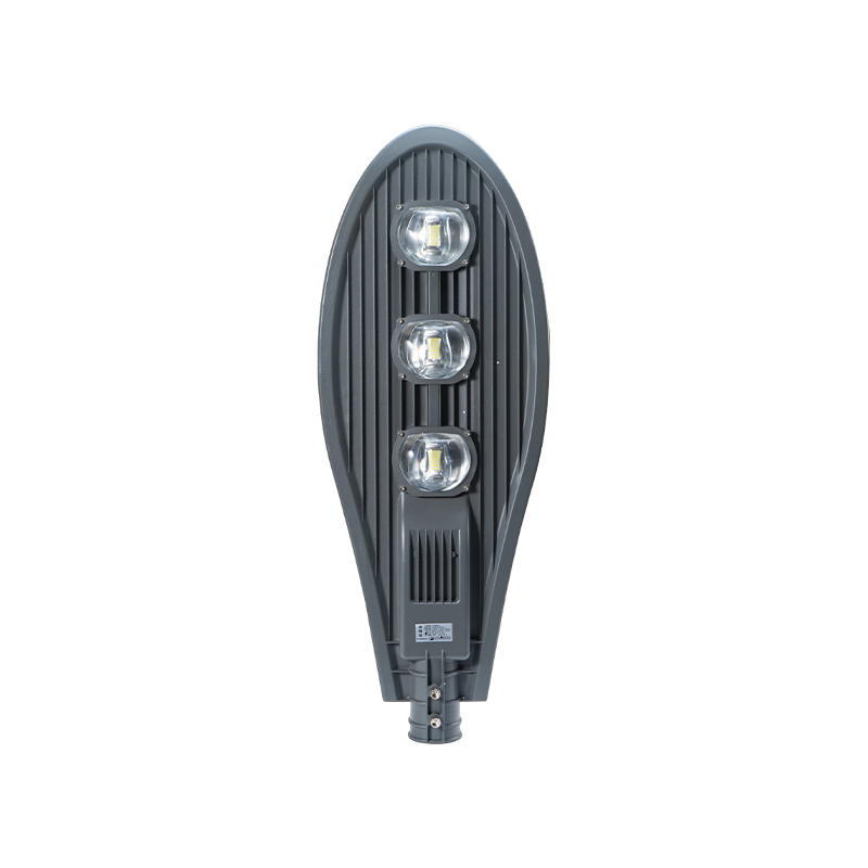
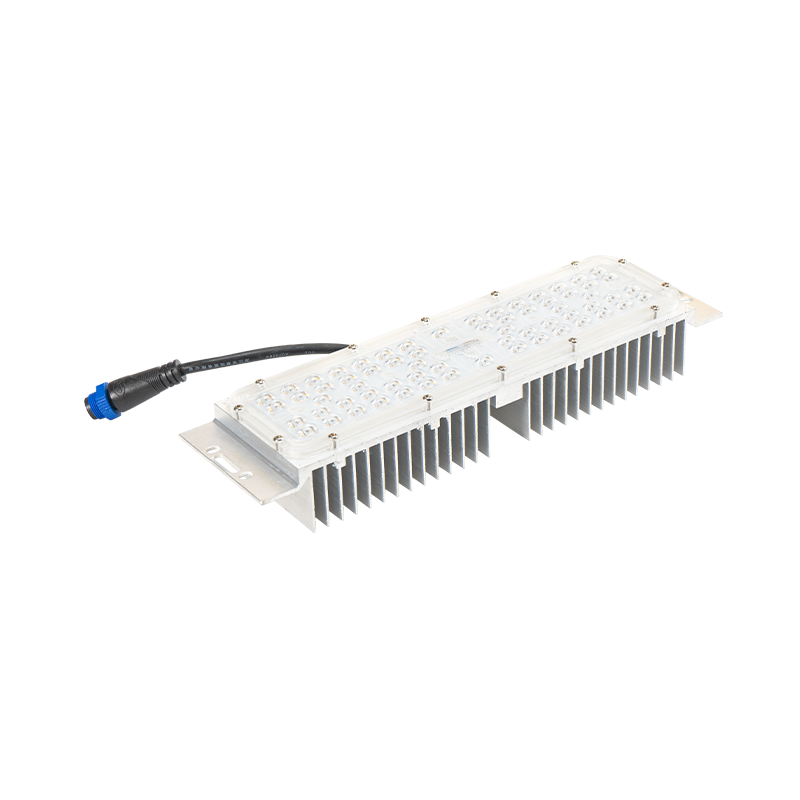
Light sources on these systems commonly range from four hundred to one thousand watts per fixture, with the total number of luminaires per platform selected based on the required illumination coverage for the specific site, whether that involves a highway interchange, a stadium perimeter, or a shipping terminal. Optical components within each luminaire are arranged to concentrate and distribute light evenly across the target area while limiting glare that could affect drivers or pedestrians below, a design consideration that becomes more significant at greater mounting heights where beam angle spread covers a wider ground area.
Electrical Wiring and Grounding Connections
Electrical supply cable is routed from the underground conduit embedded in the foundation up through the interior of the pole shaft to a junction box near the base, then continues to the lighting platform through internal cabling or, in raise-lower systems, through a cable reel that accommodates the platform's vertical travel without straining the connections. A separate circuit typically feeds the winch motor used for raising and lowering the platform, requiring its own protective breaker distinct from the lighting circuit.
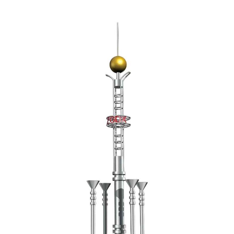
Grounding is addressed at multiple points throughout the system, since a tall metal structure standing in an open area presents a lightning strike risk that needs a defined path to earth. A grounding conductor connects the pole base to a grounding electrode installed in the foundation area, and continuity between the pole, the platform, and each luminaire housing is verified during installation to confirm that the entire structure shares a common ground reference. Local electrical codes generally specify minimum grounding electrode resistance values, and this figure is measured with a ground resistance tester before the installation is signed off.
Electrical Checks Before Energizing
- Continuity verified between pole, platform, and luminaire housings
- Ground resistance measured against local code requirements
- Winch motor circuit separated from the lighting circuit
- Cable reel or internal wiring checked for slack during platform travel
Testing the Raise-Lower Mechanism and Final Commissioning
Before a high mast system is considered complete, the raise-lower mechanism, where applicable, is cycled through a full range of travel to confirm the winch motor, cable, and guide system operate smoothly without binding or excessive cable slack. Limit switches that stop the platform at the top and bottom of its travel range are tested to prevent over-winding or the platform striking the pole base during lowering. Once mechanical operation is confirmed, the lighting circuit is energized and each luminaire is checked individually for proper operation, correct aiming angle, and consistent light output across the platform.
A final structural inspection typically reviews anchor bolt torque, weld quality on any field-joined sections, and the condition of the galvanized coating for any damage that occurred during transport or erection, since a compromised coating at even a small point can allow corrosion to begin in an otherwise protected structure. Documentation from this commissioning stage, including torque values, ground resistance readings, and photographs of the completed installation, is generally retained for future maintenance reference.
Common Applications Where This Installation Approach Applies
High mast lighting installations of this type appear in urban plazas where a single pole can illuminate a wide gathering space more efficiently than multiple shorter poles, and at transportation hubs such as bus terminals and rail yards where consistent overnight visibility supports both passenger safety and vehicle movement. Ports and shipping terminals rely on this lighting category to cover container yards and loading areas where equipment operators need clear visibility across a broad, open expanse. Highway interchanges and elevated roadway sections also make frequent use of high mast systems, since fewer, taller poles reduce the number of structures placed within the roadway median while still delivering adequate illumination across multiple lanes and ramps. Large stadiums and outdoor event venues apply similar poles around their perimeter to provide security lighting across parking areas and approach paths without introducing glare that would affect nearby residential areas or drivers passing the venue.
Comparing Installation Considerations by Site Type
Different installation sites bring different practical constraints that affect how the sequence above is carried out, particularly around access for cranes and the amount of underground utility coordination required beforehand.
| Site Type | Typical Pole Height | Key Installation Factor |
|---|---|---|
| Urban plaza | 20–25 meters | Crane access in a confined public space |
| Highway interchange | 30–40 meters | Foundation depth for wind loading on ramps |
| Port or terminal | 25–35 meters | Corrosion resistance in coastal air |
| Stadium perimeter | 20–30 meters | Glare control toward seating and roadways |
Reviewing site-specific factors such as soil bearing capacity, wind exposure, and proximity to corrosive environments before finalizing pole height and foundation design helps installation proceed without unexpected delays. Coordinating with utility locators before excavation and confirming that foundation curing time is respected before erection begins are two of the more common points where rushing the schedule leads to complications later in the project.